Created Mar 07
Modified May 07
Where to start um er. Ok first off for those with rev3+ motors this is so not a straight forward fit. Anybody tells
it is should be slapped hard!! I'd heard this straight forward story and believed it so did Calum who was fitting the
darned thing. It aint straight forward. Not even close.
Ok, that particular rant over I'll explain what went pear shaped.
- the legs on the chargecooler on the gearbox side of the engine interfere with the vacuum pipes
- the core water pipes catch the top of the engine mount
- the core water pipes point in the wrong direction for the mr2
- the stock airbox and chamber get in the way of the core water pipes
- the stock catch can return vacuum pipe gets in the way of the recirc BOV
- the engine mount gets caught by the core water pipes
We chose to mount the pre-rad first purely because we figured getting that right with the pipework running to the
engine bay was going to take the most time. Ho hum. Fixing strip is just the aluminium bar. Easy to work with cheap to
buy from B+Q. You can use the existing horn mounting holes for the top support and then use the support bar to mount
the bottom solidly. Now I removed my air con unit because the compressor was gubbed and I just had no will left to
fix it. I have it on good authority that the Fiat rad fits fine in front of the air con unit but see rant above.
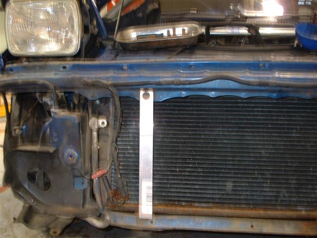
Now the other side is a bit more complex because I wanted to use the bleed valve on the rad itself but I really
shouldn't have bothered.
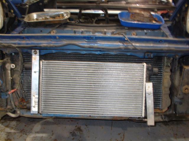
So in order to tighten that up so the rads didn't bounce off each other we fitted another strap to locate the hole
thing solidly. It's not the prettiest of installs but you don't notice with the bumper on so I don't care. It works
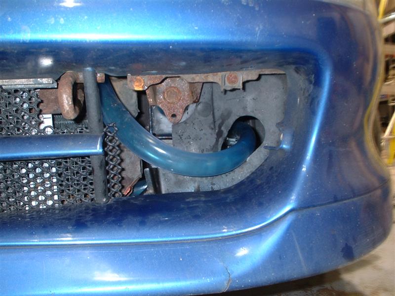
that's what matters. The one problem we do have is that we have had to run the coolant pipes from the pre rad through
mounting holes left by the fog lights. This sadly means the pipes are visible from the front of the car but it's no
biggy. When we first filled it up we had blue coolant which was fine but now we're using red stuff it kinda shows.
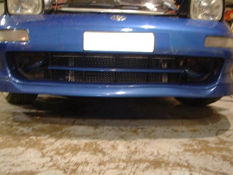
A more obvious pic, I'll get some blanking plates made up and cover the entire corner so it's no big deal.
We had issues routing the pipe back to the pump position and just couldn't figure out how to do it neatly so we
decided to route the outlet of the pre rad up and over the rad itself and then back down into the wheel arch. In
doing so we came up with a rather novel bleed valve system. It works too! If we'd thought of this sooner we could
missed out the hassle trying to mount the pre rad and just block off the bleed valve completely. Anyway, we cut the
plastic piping and then inserted a straight metal pipe which we had cut a nut and bolt arrangement into making a
bleed valve. Looks like..
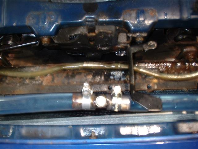
Works beautifully and if I ever fit the plastic cover back in you'll never notice it's there. It made bleeding this
thing so much easier. Run the pump for a while til you get an air lock and shut off the pump. Slacken the bolt til
the air has fully escaped and then re-tighten. Repeat until no air is there.
So where to fit the pump?? I'd really recommend fitting the pump in the engine bay somewhere. If you plumb the
outlet of the of the core into the inlet of the pump then you can pretty much remove air locks into the pump as gravity
will help keep the pump primed. The other advantage of mounting in the engine bay is easy access should anything
go funny with the pump. However, since I have the standard airbox / plenum setup I don't have any space in the engine
bay to mount the pump so mine got fitted in the front passenger wheel well. It fits fine but to get to it you have to
remove the entire bumper. Not really idea but hopefully not a future issue.
Now I bought a pump from Ebay that was touted as being suitable for a chargecooler system. I think the reasoning behind
this was the pump worked fine in Audi's and Volkswagon's coolant systems for engine shut down cooling but trust me it just
aint got the grunt for use in a chargecooler system. My first Ebay pump was like rated at 1200Litres per hour and 1.5 AMPS
looked like...
In testing it looked like it was flowing enough coolant but temperature data proved it was far from up to the job. I
tried one of the Bosch AVT units rated at 1330Litres per hour and 4 AMPS and yes it was better but not by much. The Celica
unit has been tested at 2880Litres per hour and 12AMPS so I took the plunge and bought that. It's HUGE as below
It's pipe layout is also different enough that it caused a few issues with the pipework but in the end we ended up with
something that works fine. Previously I had issues with the intake temperatures at idle just rising out of control and
only coming back on target when the car was rolling. Now with the Celica pump in situ the idle temps stay very stable at
around 30degC. Under boost they are rising to the low 40degC mark but that's on a std CT20b running 17odd psi. Not the
most efficient turbo at that pressure. The pump is wired to run full time and the power is feed via a relay that's
powered straight off the battery and the relay is switched on by the radiator fan control feed. It's on the live side
so even if the fuse blows the chargecooler pump will still get power. This will get a more perm and variable speed
controller wired in eventually. Right now I'm exhausted from the work and it's working well now so more pressing things
can get done now.
Anyway, the coolant pipes are lagged with cable tidy to protect them where they go through the foglight holes and
hopefully sometime soon I'll get the blanking plates made up and that will tidy up the front end.
Now how Calum ran the pipes from the pre rad to the engine bay I have no idea. He basically jacked the car up and
ran the pipes down the side of the existing pipes. The area around the steering rack was a pain but he managed it
without a big song and dance. We both had that with the engine bay hassles lol. Now in theory you want to keep the
chargecooler pipes well clear of the existing coolant pipes as they are running a good bit hotter but in reality
there is no heat transfer between the sets of pipes. At least none I can measure anyways.
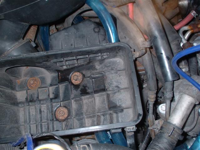
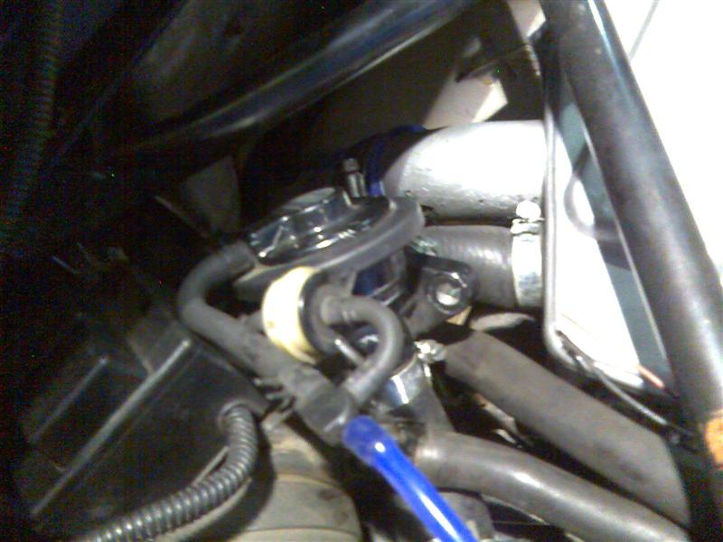
Right o mounting the core. A good idea is to see where the core and plastic coolant pipes run into the bay so you
can see how you are going to join. First off you want to remove the mounting legs on the core itself. Now I don't
think you actually need any of the mounts since the pipe out of the turbo and the pipe into the throttle sock will
hold the core pretty solid. That and the throttle cable too. These mounts do get in the way so no way can they stay.
Pic below explains
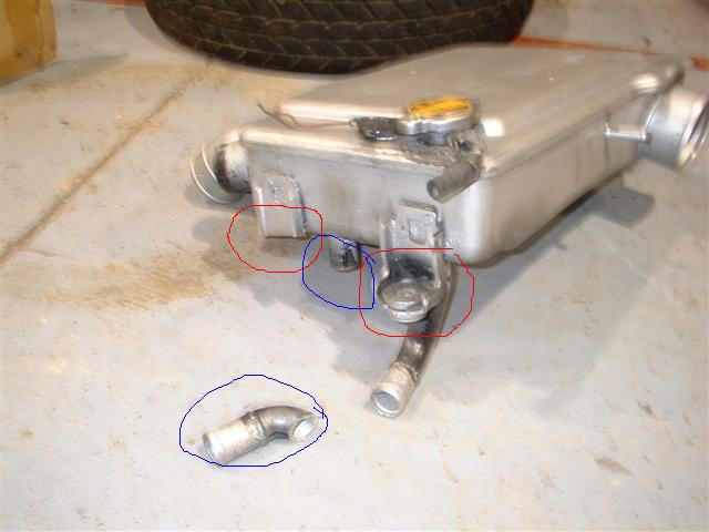
The red circles show the core mounts to remove and the blue shows the coolant leg that we removed then had to reweld
at a different angle in order to stop the plastic piping from bending. The external diameter of those coolant pipes
is 22mmOD. Yes using the 19mmID piping worked but off the shelf they have no available 45 or 90deg bends and this
made so much more work for us that we could have thought. Thinking back on it, it may have been easier just to remove
the core pipes where they started curving then relying on the plastic piping to do the bends but that's the
benefit of hindsight for you.
So using here's one we prepared earlier you can see the pipes coming out of the core and joining with the underbody
pipes
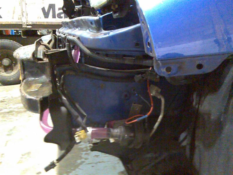
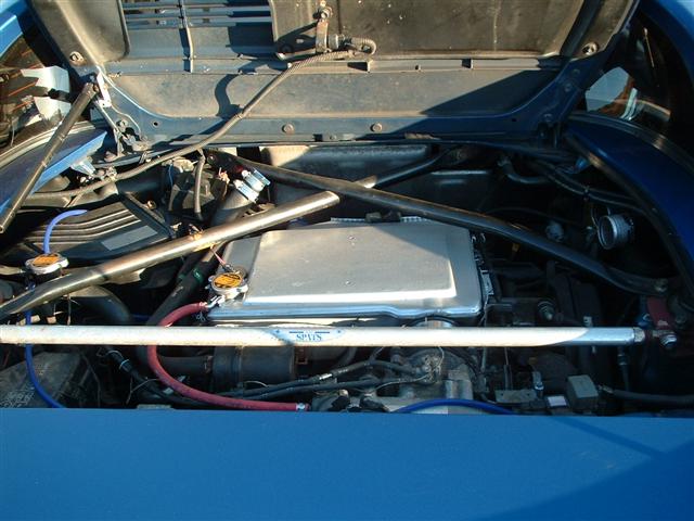
The finished article shows you what a nightmare the plumbing is. Basically you need to remove the airbox and piping
which then allows you to get to the coolant pipes from underneath and then pull them up into the engine bay. You then
fit the airbox bottom back in and you end up with as below.
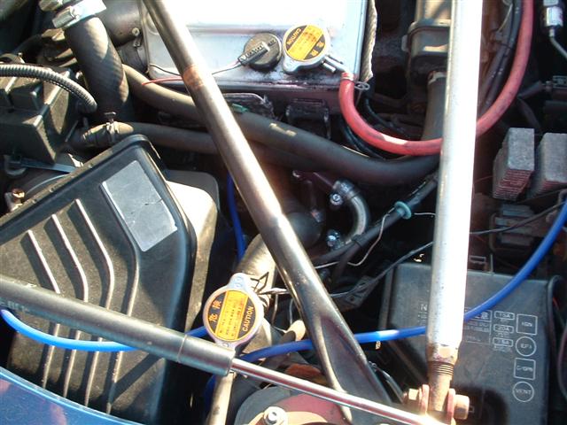
Ok so with the core sitting in place and the underbody coolant pipes pulled through you now have to figure out how
join the blighters together. Due to the design of the core and the filler location the cold inlet from the pump
goes into the core pipe furtherest from the filler and the hot outlet from the core is thus under the filler cap.
You still have a fair bend to get through and after much head scratching and playing with flexible pipes we found
a pair of these little beauties to solve our issues
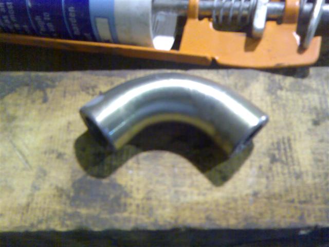
Those 90deg bends were actually cut out of a hydraulic pipe we had and even then they aint quite the right size. That
19mmID causing yet more grief but with Jaffa strength they were made to fit. First off squeeze a small length of plastic
piping onto the core pipes, then add the 90deg bends which then join onto the under body pipes. Providing you remember
which way round the pipes need to connect and which is which! After fecking it up once I now have black tape on one
set of pipes so I don't have that grief again.
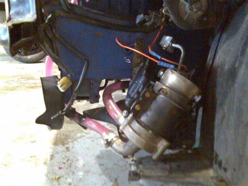
Below is a pic of the finished core install with the BOV still to be plumbed back into recirc mode.
Ok so now we have the core plumbed in and we're happy with it. That vent to atmosphere BOV however just has to be
plumbed back into the airbox cause I can't stand the noise it makes. Attracts too much attention as well because
at -1.5psi to +2ish psi the BOV doesn't actually close so it kinda sounds like a jet turbine which aint subtle. Give
me quiet BOV anyday. Ok, so you take the std BOV pipe and attach it to the core dump vent, then you plumb in the
catch can pipe too then the vacuum feed back into the air intake piping so now you have all the pipes in place. Now
bend the BOV piping til you can attach the BOV itself, the flow is into the side of the BOV and out through the centre
bore ie, the opposite from a centrifugal pump like the water pump used in this conversion. Mark the piping with a pen
and then cut the piping to size. Plump the BOV into the core side of the system then the other cut length is used to
plumb it back into the airbox. It's tight so don't have the BOV sitting higher than it needs to be otherwise you won't
have the length to reach back to the airbox.
It's a bit of a push / pull but you can see from the picture above the lay of the pipework and providing you have cut
the pipes correctly you will get the BOV on without any trouble. I initially thought I'd cut the core to BOV pipe too
long but I got away with it in the end. I'll measure the cut if I get the chance.
The last task is to plumb in the overflow pipe so it has a wee reservoir incase the core pressure cap decides it needs
it. Irn Bru bottle at the ready for that one I think lol.
Still to come are the results of testing and the justifcation for changing the pumps. ho hum, more expense